CAD means Computer Aided Drafting
which is the method to draw the various engineering drawings by using computer
software. Among the various designing software, CAD is very effective and
productive in the designing field for all engineering fields like civil,
electrical, architecture and mechanical. There are some free software for
students (for software click here) and tutorials (for
tutorial click here).
Tips: There are
following 3 basic tips for doing CAD design effectively for a starter to become
a professional designer.
1)
First you have to gain the product knowledge which you want to design, material
data, measurement data and user data.
2)
Then you can design in a paper for rough sketch and note that all data for
record which will help you drawing.
3)
And finally you have to start you drawing in cad software. Off course cad
software is easy but to learn you have to be little passionate as well as
curious and need to give time for learning. Once you get the fun then you will
learn fast.
Start
a Drawing: Here
in below I am giving the startup process of autocad software for beginners with
picture with a short example. First open the autocad in your computer (considering
that autocad is well setup in the learner computer). In the left top we have
a big red colored AutoCAD. By clicking this button we
can have different option. One of these options is to start new drawing.
- Units Settings: After getting
the new window to draw then you can draw your desired drawing but by default
the unit used in the drawing is inch. You can also change the unit
setting of the drawing by entering the unit key into the command
window. After entering the command you will get the block appeared
in window named Drawing Unit. By changing the Insertion
Scale you can change the used unit in your drawing. There are many
more options regarding units so you can select then according to your
requirement.
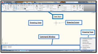
- There is Tool Bar on the top of the window; there are different tabs to approach different tools with variable drawing options.
- Drawing Cursor is use to draw the drawings and also used to select the tools and other various options.
- In the Drawing Area drawing can be drawn with help of cursor by using required tool.
- Command Window is very impotent area placed in the bottom of the software window, where we can enter the keys of different tools to select and also put there dimensions in drawing area.
- For the selection of the drawing type like 2D Drafting & Annotation, 3D Modeling, AutoCAD Classic etc. there is option in right bottom of the window.
- Function of Snap to Grid-cursor snap to grid
point
- Function of Show Grid-display grid in model space
- Function of Orthographic-constrains lines to 90deg angles
- Function of Polar Snap-constrains lines to other angle increments
- Function of Dynamic UCS-show UCS at all times
- Function of Dynamic Input-displays input text in space
- 2D Commands: Line(L), Rectangle(rec), Circle(c), Polyline(pl), Trim(tr), Extend(ex), Offset(o), Move(m), Mirror(mi), Scale(sc), Rotate(ro).
- 3D Commands: Extrude(ext), Union(uni), Subtract(su), 3D Rotate(3r).

- A Short Example:
 · Select the line
command from the tool bar or write line in the command window then select the
coordinates to start the line. Coordinates can be given by clicking the courser
or by putting the values (x,y) in the command window.
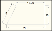
· Try left side sample drawing including only line command with annotation. (You can
select Ortho Mode for your easiness to draw perpendicular lines).
· After
selecting the starting coordinates move the courser to right side towards which
you have to draw the line and upside of the line there is a digital value which
indicates the length of line. You can put it 20 by numerical buttons of laptop
or desktop and then press enter button. There is also indication of angle of
line on the courser from the horizontal line.
· Now
move the courser in upward direction to draw the next line which is
perpendicular to the previously drawn 20 line. Put the value of 10 and press
enter to add the line.
· Move
you courser to the left side to draw the line having 15 in length. Now
move your courser to the starting point to end the required drawing. You can
also see the angle (here it is 117o) of your drawing which is being drawn in this step.
· After
clicking the start point which is actually end point of drawing. The option of
drawing line is on by default, so you can press esc or enter button to end the
command. To end you will get the drawing as per given view. Try more drawing to get sharp and swift hand and mind for design.

