Stress-strain-deflection simulation in SolidWorks typically
involves using Finite Element Analysis (FEA) to analyze how a part or assembly
responds to external loads. In this case, you want to study how a component
deforms (deflection) under applied loads while also understanding the stress
and strain distribution within the material. Here's a step-by-step guide on how
to perform such a simulation in SolidWorks:
- Create
or Import Your Model:
- Start
by creating your 3D model in SolidWorks or import an existing one. Ensure
that the material properties are accurately defined for the parts you
want to analyze.
- Apply
Loads and Constraints:
- Define
the boundary conditions by applying loads and constraints to your model.
Common boundary conditions include:
- Fixing
some faces or edges (restraining movement).
- Applying
forces, pressures, or torques on specific surfaces or points.
- Adding
connectors for assemblies if necessary.
- Define
the Study:
- In
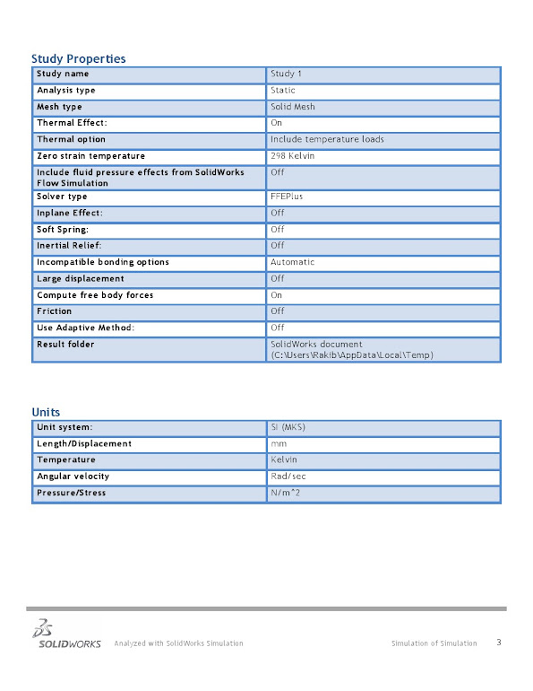
SolidWorks, go to the Simulation tab and create a new study. Choose
"Static" for a basic stress analysis.
- Assign
Materials:
- Assign
appropriate materials to your model. You can choose from SolidWorks'
material library or define custom materials with specific properties.
- Mesh
Your Model:
- Divide
your model into smaller elements by meshing. The quality and size of the
mesh affect the accuracy of your simulation. Use automatic meshing or
refine it manually if needed.
- Define
Simulation Properties:
- Set
up the analysis type (linear or nonlinear) based on your material
behavior. Linear analysis assumes small deformations and material
behavior, while nonlinear analysis considers large deformations or
nonlinear material behavior.
- Run
the Analysis:
- Click
the "Run" button to start the simulation. SolidWorks will solve
the equations governing the behavior of your model under the applied
loads and constraints.
- Review
Results:
- After
the simulation is complete, review the results. You can view stress,
strain, and deflection plots as well as other relevant data such as
safety factors, displacement, and reaction forces.
- Interpret
the Results:
- Analyze
the results to determine whether your design meets your requirements. Pay
attention to areas of high stress or excessive deflection, which may
indicate design weaknesses.
- Iterate
and Optimize:
- If
necessary, make design changes based on your analysis results to improve
the performance of your model. Then, repeat the simulation to validate
the changes.
- Generate
Reports and Documentation:
- SolidWorks
provides tools to generate reports summarizing your simulation results.
You can use these reports for documentation and design validation purposes.
- Save
and Archive:
- Save
your simulation setup, results, and any relevant files for future
reference.
SolidWorks offers a wide range of advanced simulation
capabilities beyond this basic guide, including dynamic analysis, thermal
analysis, and more. Depending on your specific needs and the complexity of your
project, you may need to explore these advanced features. Additionally, always
ensure that your simulation setup accurately represents the real-world
conditions and materials for your design.


